Updated: October 2, 2024
ESD Warning

This procedure involves opening G7, which is susceptible to damage from an electrostatic discharge (ESD) event. Personnel performing this procedure or handling the internal parts of cartridges must be grounded.
Overview
This article describes how to complete the PID Sensor Lamp cleaning procedure for diffusion cartridges.
CAUTION: This procedure is intended for G7c and G7x Diffusion cartridges only. Do not attempt this procedure on a G7c or G7x Pump cartridge, as it can permanently damage the cartridge and void your warranty. PID sensor lamp cleaning for a G7c and G7x Pump cartridge must be performed by technicians trained on the procedure. Please contact Technical Support for more information.
Use this procedure to clean the 10.6eV PID sensor lamp for the following equipment:
- G7c and G7x Diffusion single-gas cartridge
- G7c and G7x Diffusion multi-gas cartridge
- EXO multi-gas cartridge
This article contains the following sections:
- Important Information
- When to Clean the Lamp
- When to Replace the Electrode Stack
- Required Tools and Parts
- Removing the Cartridge - G7c and G7x
- Removing the Cartridge - EXO
- Removing the PID Sensor
- Removing the Lamp and Electrode Stack
- Cleaning the Lamp
- Reassembling the Electrode Stack, Lamp, and Body
- Reassembling the Cartridge
- Replacing the Cartridge
Important Information
The following procedures must be performed in a clean environment, as the equipment is sensitive to contaminants.
CAUTION: PID lamp cleaning should only be performed by technicians trained on the procedure.
The PID is a sensitive sensor, and the lamp is fragile. Handle the PID sensor with extreme care. Use gloves and clean tools to handle the internal components. Never touch the window.
WHen to Clean the Lamp
The PID uses an ultraviolet light source to ionize VOC gases as they pass across the lamp window. This process may result in a fine layer of contamination on the detector window that must be removed on a regular basis.
The lamp should be cleaned every 100 hours with normal use of the sensor (based on 30 ppm for 100 hours). If G7c, G7x, or EXO is used in heavily gas contaminated environments, clean the lamp more often.
Some esters, amines, and halogenated compounds may accelerate window fouling. In these cases, lamp cleaning may be required for every 20 hours of use. The frequency of cleaning also depends on set threshold levels and prevailing environmental conditions.
Resolve this problem by cleaning the lamp using the following procedures.
WARNING: To ensure that the sensor operates correctly, replace damaged lamps immediately.
Required Tools and Parts
To perform this procedure, you need the following tools and parts:
- PID cleaning kit (ACC-PID-CLEANING KIT)
- PID stack removal tool (ACC-PID-REMOVAL-TOOL)
- Electrostatic discharge (ESD) wrist straps
- Torque-limiting Torx screwdriver set to 3.3 in-lbs or 0.37 nm for G7c/G7x
- Phillips screwdriver for EXO
- Latex or Nitrile gloves
- Can of compressed air
- Tweezers
You may also need the following replacement parts:
- PID Lamp 10.6eV (ACC-PD-LAMP)
- Blue PID Stack (ACC-PD-STC)
- PID Spring (ACC-PD-SPR)
- Single Gas Filters (ACC-S-FILT10-INT)
- Quad Gas Filters (ACC-Q-FILT10-INT)
Removing the Cartridge – G7c and G7x
To remove the cartridge from G7c or G7x:
- Power off G7c or G7x.
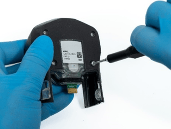
- Use the Torx 6 screwdriver to remove the screws on the sides of the cartridge and set them aside.
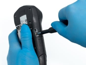
- Pull upwards on the cartridge to release it from G7c or G7x.
- Proceed to Removing the PID Sensor.
Removing the Cartridge – EXO
To remove the cartridge from EXO:
- Power off EXO.
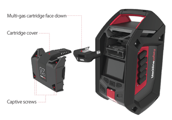
- Use a Phillips screwdriver to unscrew the cartridge cover screws.
NOTE: These are captive screws and should stay attached to the cartridge cover. - Pull forward on the cartridge cover to remove and set aside.
- Pull the cartridge out of the cartridge slot.
- Proceed to Removing the PID Sensor.
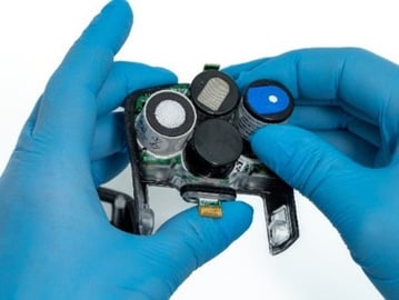
Removing the PID Sensor
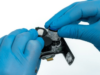
To remove the PID sensor from the cartridge:
-
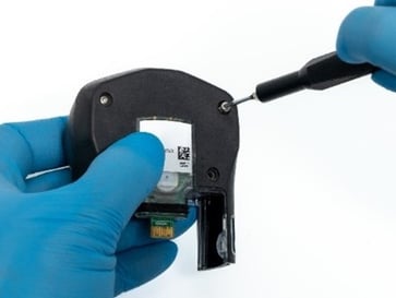
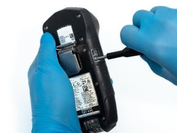
Remove the screws on the back side of the cartridge and set aside.
-
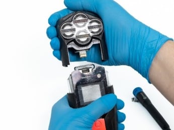
Hold down the SureSafe PCB and separate the front and back sides of the cartridge by gently pulling them apart.

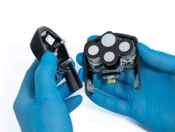
-
Remove the filter and set it aside. If you don't see the filter on the cartridge, it may be in the sensor socket.
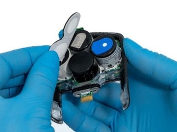
-
Carefully lift the MiniPID 2 sensor from the cartridge.
Removing the Lamp and electrode stack
CAUTION: To avoid damaging the equipment, use the electrode stack removal tool. Any other tools (for example, screwdrivers) may damage the MiniPID 2 sensor body and invalidate your warranty.
Wear latex gloves while performing the following steps.
To remove the lamp and stack:
-
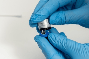
Position the electrode stack removal tool in the side slots of the MiniPID 2 sensor.
-
Holding the stack on the top and bottom with one hand, gently squeeze the stack removal tool sides together with the other hand until the electrode stack and lamp are released.
NOTE: Holding the top and bottom of the stack prevents the spring from releasing too quickly, which could cause it to fall out and get damaged.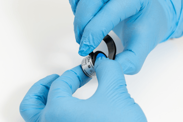
-
Carefully lift the MiniPID 2 body away from the electrode stack and lamp. Set aside the electrode stack and lamp. NOTE: Occasionally, the lamp may remain in the MiniPID 2 body and must be carefully freed by tipping the MiniPID 2 body on its side. If the spring behind the lamp comes out when the lamp is removed, check the spring for damage and replace it into the MiniPID 2 body. If the lamp is lodged in the MiniPID2 body, carefully work it free with tweezers. Set aside the lamp and electrode stack.
-
Use a clean cotton bud to gently rub the top of the MiniPID 2 body to clean the connections.
-
Holding the MiniPID 2 body upright, blow compressed air inside the MiniPID 2 body to remove any dust. Set aside the MiniPID 2 body.
NOTE: Ensure you hold the MiniPID 2 body upright when you are using the compressed air, as holding it on its side or upside down may cause the spring to dislodge and get damaged.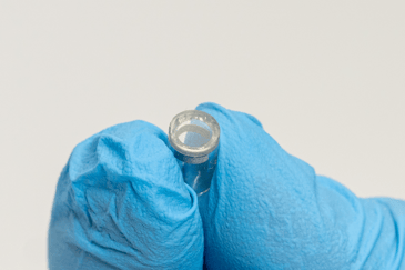
-
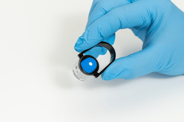
Use tweezers to carefully remove the lamp from the O-ring in the underside of the electrode stack. Set aside the electrode stack on a clean, flat surface, with the flat side down.
-
Check for contamination on the detection window by holding the lamp in front of a light source and looking across the window surface at an angle. Any contamination will appear as a "blue hue."
-
Check the lamp and window surface for damage, pits, cracks, etc. Replace the lamp if any of these issues are found.
IMPORTANT: Do not use a PID sensor with a damaged lamp. The PID sensor will not work if the lamp is damaged. Damaged lamps must be replaced. Contact Blackline Technical Support for assistance.
Cleaning the Lamp
Handling and Storage of the Polishing Compound
WARNING: The polishing compound contains aluminum oxide (CAS Number 1344-28-1) as a very fine powder, which may irritate your respiratory tract and eyes. A full material safety data sheet MSDS is available on request. Contact Blackline Technical Support for assistance.
The polishing compound has a TVL (TWA) of 10 mg/m3.
Handling:
- Do not breathe the vapor/dust.
- Avoid contact with skin, eyes and clothing.
- Wear suitable protective clothing.
- Follow industrial hygiene practices: wash face and hands thoroughly with soap and water after use and before eating, drinking, smoking, or applying cosmetics.
Storage:
- Always replace the lid after using the polishing compound.
- Keep the polishing compound container closed when not in use to prevent water adsorption and contamination.
To clean the lamp:
WARNING: Wear latex gloves while performing the following steps.
CAUTION: Never touch the lamp window, even with gloves.
-
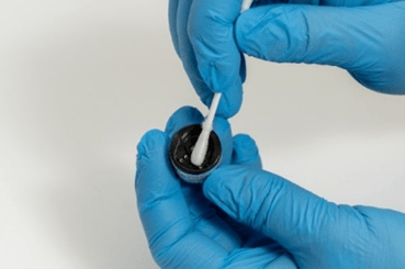
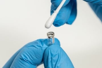
Open the container of aluminum oxide polishing compound.
-
Use a clean cotton bud to collect a small amount of the polishing compound.
-
Using a circular motion and applying light pressure, use the cotton bud to clean the lamp. Do not touch the lamp window with your fingers.
CAUTION: Never use a side-to-side or up-and-down motion when polishing the lamp, as this can scratch the lamp.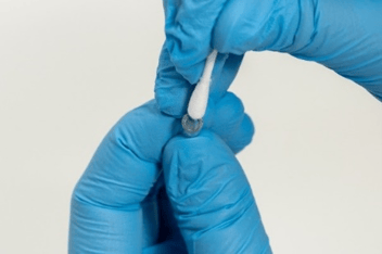
-
Continue polishing with a circular motion until you hear a “squeaking” sound when the cotton bud moves over the window surface. This usually requires 15 to 30 seconds of polishing.
-
Use a clean cotton bud to remove the residual powder from the lamp window.
-
Holding the lamp, use compressed air to remove any remaining polishing compound.
-
Check that the window is clean by holding the lamp in front of a light source and looking across the window surface at an angle.
-
If the lamp window still appears dirty, follow the above steps to clean it again.
-
If the lamp window appears scratched, replace it with a new lamp.
Reassembling the Electrode Stack, Lamp, and Body
To reassemble the PID sensor electrode stack, lamp, and body:
-
Place the new electrode stack onto a clean, flat surface, with the electrode stack facing downwards.
-
Carefully twist the detection window end of the lamp into the O-ring around the well in the underside of the electrode stack. The lamp window should sit flush within the electrode stack.
WARNING: Confirm that the lamp is firmly held in the electrode stack with the detection window level with the electrodes. If the lamp is placed incorrectly, the O-ring can become trapped between the window face and the electrode stack, resulting in inconsistent and unreliable VOC readings.
- Carefully align the MiniPID 2 body over the electrode stack and lamp.
- Push the MiniPID 2 body down until you hear two clicks to secure the assembly.
NOTE: Be careful when pushing down that your latex gloves do not get caught between the electrode stack and the MiniPID 2 body.
- Inspect the sensor to confirm that both wings of the electrode stack have engaged with the MiniPID 2 body.

Reassembling the Cartridge
To reassemble the cartridge:
-
Refit the sensor back into the cartridge.
-
Place the filter over the sensors with the black ring facing out. Ensure that that filter's largest circle is located at the top.
- Inspect the cartridge gasket, located on the front shell, to ensure it is seated correctly.
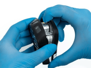
-
Hold down the LED chip and align with the groove.
-
Slide the front and back of the cartridge together, holding it in place.
CAUTION: Be careful when sliding the front and back of the cartridge together. If the LED light is not held down, the light can be damaged which may cause complications with your SureSafe light.
- Replace the screws into the back of the cartridge, turning until the screws are tight and the cartridge is securely together.
Replacing the Cartridge
To replace the cartridge in G7c and G7x:
-
Slide the cartridge down onto the device.
-
Replace the two screws on either side.
-
Calibrate the cartridge. For detailed calibration steps, see the G7 Technical User Manual.
To replace the cartridge in EXO:
-
With the cartridge sensors facing down, push the cartridge into the cartridge slot.
-
Replace the cartridge cover.
-
Tighten the screws.
-
Calibrate the cartridge. For detailed calibration steps, refer to the EXO Technical User Manual.


